

Introduction
I have been wanting to write this blog for quite some time, either I was busy or lazy. I have been asked by so many people on the list of hardware to buy to get started with hardware hacking. To be honest, there are a lot of products available, but not many target beginners.
In this blog i will cover about using SPI, I2C, JTAG/SWD and JTAGenum using Raspberry Pi. I will be using Raspberry pi zero w, as it is dead cheap and small.
Setting up your Raspberry Pi
Before you go into each section, I would suggest you boot into your raspberry pi and enable SPI, I2C, GPIO from the interfacing options in the raspi-config menu. You can follow this link for setting up your Pi.
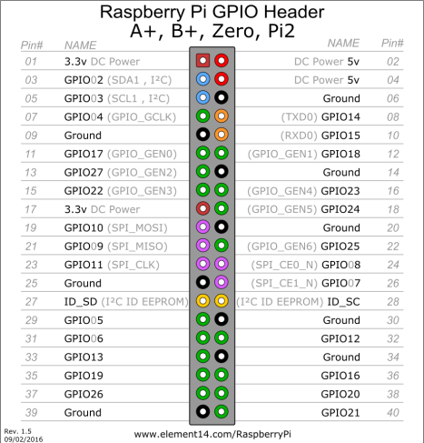
In all the connection pinouts, It is the hardware pin location and not the GPIO number.
Git clone this inside your pi
https://github.com/arunmagesh/raspi-sec-tool
SPI – Serial Peripheral Interface
Raspberry Pi comes with SPI interface, Most common test case in hardware testing is to extract the external flash memory of the target device which uses SPI communication interface. Most commonly used tool is flashrom which supports a wide variety of flash memory support. We are going to utilize the bcm2385 SPI interface /dev/spidev0.0 for reading and writing to it.
Installation:
sudo apt-get install build-essential pciutils usbutils libpci-dev libusb-dev libftdi1 libftdi-dev zlib1g-dev subversion libusb-1.0-0-dev
svn co svn://flashrom.org/flashrom/trunk flashrom
cd flashrom
make
Connection:
CS – 24
MISO – 21
MOSI – 19
CLK – 23
3.3v – 17

To read data from the flash memory
flashrom -p linux_spi:dev=/dev/spidev0.0,spispeed=512 -r spi_dump.bin

Don’t forget the spispeed=512.
Now you can use binwalk or fmk in the extracted firmware.
I2C – Inter-IC Communication
This communication is similar to the SPI, but it uses only two wire for communication – SDA/SCL. Each device is accessed by using their internal i2c address. Here we will use an I2C EEPROM as an example and see how we can read and write to the memory. i2ctools comes as a part of the Linux package, so no need to install anything.
Connection:
SDA – 3
SCL – 5
VCC – 1
VSS – A0 – A1 – A2 – A3 – WP – 6

To find the address of your i2c slave device.
i2cdetect -y 1

In this case, the address is 0x50. -y 1 defines which i2c pins you have used. in this case, we are using i2c-1.
Now use a tool called as eeprog to read and write to the EEPROM.
wget http://darkswarm.org/eeprog-0.7.6-tear5.tar.gz
tar -xvf eeprog-0.7.6-tear5.tar.gz eeprog-0.7.6-tear12/
cd eeprog-0.7.6-tear12/
make
sudo make install
To write data to it
echo “hello” | ./eeprog -f -16 -w 0 -t 5 /dev/i2c-1 0x50
-w is the offset
-t is write delay

To read data from it
./eeprog -x /dev/i2c-1 0x50 -16 -r 0x00:0x10

Debugger – JTAG/SWD
JTAG/SWD are standards which allow developers to debug any microcontroller or microprocessor. From an attacker perspective having access to the debug means game over for the device. An attacker can dump the internal memory or do changes in the memory dynamically. Let’s talk about accessing both JTAG and SWD using just a Raspberry pi. We use an opensource tool called as openOCD which talks to the debugger.
Connection:
JTAG:
TCK – 23
TMS – 22
TDI – 19
TDO – 21
SRST – 12
GND – 20
SWD:
SWDIO – 18
SWCLK – 22
SRST – 12
GND – 14
To Install openOCD
git clone git://git.code.sf.net/p/openocd/code openocd
cd openocd/
./bootstrap
./configure –enable-maintainer-mode –enable-bcm2835gpio –enable-sysfsgpio
make & sudo make install
It will take some bit of time, so be patient.
JTAG:
The Configuration file for JTAG comes with the openOCD package itself. just running this with target cfg will connect to it’s JTAG
openocd -f interface/raspberrypi-native.cfg -f target/stm32f4x.cfg

Now you can connect to gdb and debug the device.
SWD:
openocd -f raspberrypi_swd.cfg -f target/stm32f4x.cfg
raspberrypi_swd.cfg is located in the git you downloaded earlier.

Now you can connect to gdb and debug the device.
JTAGenum
In a typical device, it is rare to find the JTAG interface and where the pins are located. So we use a tool called as JTAGenum which scan for all the pins the devices and tell you which pins is TMS-TCK-TDI-TDO. This is very helpfull if you don’t have proper documentation of the target device.
Installation:
git clone https://github.com/cyphunk/JTAGenum
cd JTAGenum
source JTAGenum.sh
scan
Pins to be used are 3 – 5 – 7 – 11 – 13 – 15 and common ground.
This will take a bit of time as the GPIO is quite slow.

Successful find.

Time it took for me.

That’s all for now guys. I will update more if I find more information on using Raspberry Pi as other cool things.
We have created a shield for doing the same without messy wire. You can get one if you happen to catch hold of Aseem Jakhar.

Reference:
- https://github.com/cyphunk/JTAGenum
- https://github.com/synthetos/PiOCD/wiki/Using-a-Raspberry-Pi-as-a-JTAG-Dongle
- http://catch22.eu/baremetal/openocd_sysfs_stm32/
- https://movr0.com/2016/09/02/use-raspberry-pi-23-as-a-jtagswd-adapter/
- https://www.richud.com/wiki/Rasberry_Pi_I2C_EEPROM_Program
- https://libreboot.org/docs/install/rpi_setup.html

