

Hello Everyone and Welcome !!
In this blog series, we will be learning about Radio Frequency (henceforth RF) theory, various modulation techniques and how to analyze them.
Since the topic is huge, we will cover RF basics and theory in this part. Also, instead of using technical terms and definition, I will be using simple words to make you understand any topic/concept easily.
Why we should study RF ?? – Internet of things – IoT, we all have heard this term right??
The popularity of IoT and all the devices getting connected wirelessly is imminent in today’s life. The majority of these devices will communicate with each other wirelessly using radio protocols ( frequency range ~ 3 kHz to 300 GHz). IoT devices use different Radio protocols such as ZigBee, RFID, Bluetooth etc. for communication.
If we go back in time, many vulnerabilities have been found and exploited in IoT devices using some sort of radio communication. So, for pentesting IoT devices we need to have a strong foundation of various radio protocols, how they communicate and different modulation schemes they use for communication. Thus, analyzing radio communication is of utmost importance from a security point of view and cannot be taken for granted.
So let’s start.
Short Theory on Electromagnetic Waves – Majority of IoT devices communicate over wireless protocols. Since they are communicating wirelessly, they may be using some kind of waves to communicate with each other. These waves are called Electromagnetic Waves.
Electromagnetic waves can be Radio waves, Microwaves, Infrared radiation, visible light, Ultraviolet light, X-rays etc. So what is that 1 factor which classifies Electromagnetic waves into different types?
The factor is Frequency.
More on frequency later.
So based on the frequency, Electromagnetic waves can be Radio waves, Microwaves, Infrared radiation, visible light, Ultraviolet light, X-rays etc.
If the frequency at which a wave is oscillating is between 3 KHz to 300 GHz, then it is a Radio Wave communication and the waves are called Radio Waves.
We will restrict our discussion to Radio Waves.
RF Theory and Terminology –
- Frequency – In simple words, frequency is the no. of cycles a radio wave completes in a given time duration. Usually the time duration is measured in seconds. So the no of cycles per second is the frequency of the radio waves.

In the above diagram, we can see 3 cycles per second. Thus, the Frequency of the radio wave is 3. The unit of frequency is Hertz and it is denoted as Hz. Thus the frequency for above radio wave is 3 Hz i.e. 3 Hertz.
Radio frequencies are described as multiples of hertz –
- KHz, kilohertz : thousand cycles per second.
- MHz, megahertz : million cycles per second.
- GHz, gigahertz : billion cycles per second.
- Wavelength – Wavelength is the distance between two consecutive high peaks (high points) or low peaks (troughs) in a wave. In the pic shown below – wavelength is the distance between 2 high peak and the peak has to be consecutive. Wavelength is denoted as lambda (λ)

- Amplitude – Starting from the origin or starting position, the maximum height, which a wave attains is known as amplitude. I know this is not the correct technical definition, but for sake of understanding I have written in this manner.If you are looking for technical definition, here it is – Maximum displacement of an oscillation from an equilibrium (zero level) position, the difference between the zero level and peak or trough of a radio, sound, seismic, or any other wave.
Now go and praise my definition 😉
Picture shown below should clear the definition of Amplitude.

- Phase – Phase is a position of a single point on the cycle of a waveform. It is measured as an angle in degrees or radians. A complete cycle is 360°. As shown below, phase can be 0, 90, 180, 360 etc. So basically phase is simply the value like 0 degree, 45 degree, 55 degree and so on

- Transmitter – As the name suggests, it is a device used to generate and transmit radio waves.
- Receiver – As the name suggests, it is a device used to receive radio waves transmitted by the transmitter.
- Transceiver – A device capable of sending and receiving the radio waves is called as a transceiver
That’s the basic theory, we need for getting started with modulation and analysis of radio waves
Modulation Concepts
- Carrier Waves – We have seen the basic theory of radio waves. Now what we want to do is – transmit the radio waves (which contains our data) to the destination. So there should be some mechanism to do so. Here comes the concept of carrier waves. A carrier wave is the one with a steady waveform i.e. constant height (amplitude) and frequency. Also, as the name suggests carrier wave is used for carrying something. These carrier wave will carry our data to the destination.
- Modulation – The process of mixing/adding our data into the carrier wave is termed as modulation. This is done by varying the amplitude or frequency or phase of the carrier wave. Depending upon what is being changed, there exist different types of modulation and they can be amplitude modulation, frequency modulation and so on.
Let’s learn various types of modulation schemes.
Instead of writing about modulation schemes and their type, it’s better to go through the classification shown below and it is self-understanding.

Analog Modulation – It involves sending an analogue data signal, with an analogue carrier wave. Example – TV Signal or Radio Transmission. Let’s discuss their types –
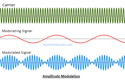
- Amplitude Modulation (AM) – The process of changing the amplitude of carrier signal according to the amplitude of the data signal is termed as Amplitude Modulation. This can be seen in the diagram below –

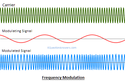
- Frequency Modulation (FM) – The process of changing the frequency of carrier signal according to the amplitude of data signal is termed as Frequency Modulation. This can be seen in the diagram below –

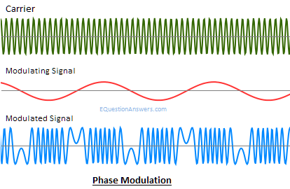
- Phase Modulation (PM) – The process of changing the phase of carrier signal according to the amplitude of data signal is termed as phase Modulation. This can be seen in the diagram below

Digital Modulation – In Digital Modulation, the carrier wave is of discrete amplitude signal. We have only 2 levels – either high (logic 1) or low (logic low). Similar to the analog, the type of digital modulation is decided by the variation of the carrier wave parameters like amplitude, phase and frequency.
Types –
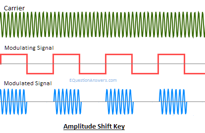
- ASK or Amplitude shift Keying – In ASK, the amplitude of a carrier wave varies in accordance with the data signal. Since it is digital modulation, information will be present, i.e. 1 or absent, i.e. 0. Thus, if the data is present it will be represented as 1 else it will be represented as 0. Thus, it is also called as on-off keying as well.

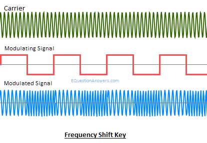
- FSK or Frequency shift keying – In FSK, the frequency of the carrier wave varies in accordance with the data signal. Thus, the frequency of the carrier wave varies as shown below –

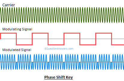
- PSK or Phase shift key – It is also called as BPSK. In PSK, the phase of the carrier wave varies in accordance with the data signal. Thus, the phase of the carrier wave varies as shown below –

These are some of the basic modulation techniques which are used in Radio Communication.
Note – Apart from these, there exist complex modulation techniques like Complementary Code Keying (CCK), Quadrature Phase Shift Keying (QPSK), QUADRATURE AMPLITUDE MODULATION (QAM), SPREAD SPECTRUM SYSTEMS (Direct Sequence Spread Spectrum (DSSS) and Frequency Hopping Spread Spectrum (FHSS)) etc. All these techniques will be discussed in an upcoming post.
Radio Signal Analysis – We have already seen various modulation techniques, now let’s analyze some radio signal for identifying the modulation being used. But, for signal analysis we need some hardware device to capture the radio signal and some software to display the signal digitally on the screen. Let’s see what hardware’s and software’s are used.
Hardware – Some device is capable of just capturing/receiving the signal and some are capable of transmitting and receiving the signal. A device which can receive/capture the signal is called as a receiver or RX and a device which can receive and transmit the signal is called transceiver or RX/TX. Below is the list of device along with the capability
| Device | Capabilities | Range |
| HackRF | RX/TX | 1MHz – 6Ghz |
| RTLSDR | RX | 24MHz-1766MHz |
| DX Patrol | RX | 100KHz-2GHz |
| USRP N-series | RX/TX | 1MHz-6MHz |
| BladeRF | RX/TX | 300MHz-3.8GHz |
| FUNcube | RX | 150KHz-240MHz & 420MHz-1.9GHz |
| SDRPlay | RX | 10KHz-2GHz |
| AirSpy R2 | RX | 24MHz-108GHz |
| AirSpy Mini | RX | 24-1800Mhz |
| LimeSDR | RX/TX | 100KHz-3.8GHz |
| YARD Stick One | RX/TX | < 1GHz |
Many hardware devices are used for Radio signal analysis but, the one’s mentioned above are widely used.
Software – Many software’s are available for radio signal analysis. To name a few we have – Gnu Radio Companion (GRC), GQRX, SDR#, Inspectrum HDSDR, Linrad, Cubic SDR etc.
In our Radio Hacking series, we will be using GnuRadio and GQRX. So I request you to download these software’s on your laptop/computer. For Linux – you can simply download from official software repository and for Windows – Google will give tonnes of resources.
That’s it for this post guys and soon I will come up with the next part. Thank You
Payatu Labs offers quality IoT penetration testing services and Practical IoT Hacking training worldwide. If you are interested in corporate training or security testing of your IoT products, kindly get in touch with us – info [_a t_] payatu DOT com
Image Sources –
http://itlaw.wikia.com/wiki/Frequency
http://cdn.ttgtmedia.com/WhatIs/images/waveleng.gif
https://c03.apogee.net/
https://physics.stackexchange.com
http://www.equestionanswers.com/notes/images/amplitude-modulation-waves.png
http://www.equestionanswers.com/notes/images/frequency-modulation-waves.png
http://www.equestionanswers.com/notes/images/phase-modulation-waves.png
http://www.equestionanswers.com/notes/images/amplitude-shift-key.png
http://www.equestionanswers.com/notes/images/frequency-shift-key.png
http://www.equestionanswers.com/notes/images/phase-shift-key.png

